
Imagine during a stakeholder meeting, a client or manager asks what if the size of this link is twice as much as it is now? Or will the product be more accessible if we move the handle down a bit? These are the sort of questions that require careful analysis and sometimes redesigning the parts and assemblies, and thus postpone the engineering decisions to the next meetings.
At the DMF Lab at the University of Bristol, we are exploring how Extended Reality (XR) can help overcome these barriers in design reviews and support more effective engineering design workflows — particularly in contexts where teams need to review, discuss, and modify real-scale assemblies and components.
Problem
Through several months of interactions with a Bristol-based design consultancy, Kinneir Dufort, we observed a recurring challenge in stakeholder-driven design processes. In many review scenarios, especially those involving large products, assemblies, or spatially sensitive systems, teams still depend heavily on physical prototypes to communicate design intent. These prototypes are valuable because they allow engineers, clients, and non-technical stakeholders to understand scale, movement, accessibility, and interaction in ways that are often difficult to grasp from conventional CAD alone. However, physical prototypes also create a significant workflow limitation: they are not easy to modify in situ.
When stakeholders request a change during a review, teams often cannot implement or test it immediately. Instead, the discussion typically shifts into a workaround mode, i.e. changes are described verbally, sketched informally, or communicated through what is often referred to in practice as “PPT CAD”: annotating or drawing over CAD screenshots in slide decks. This creates a familiar pattern of iterative communication where even small modifications may require multiple back-and-forth exchanges before they can be modelled, reviewed, and assessed properly.
XR offers a different possibility
Rather than treating stakeholder review as a largely observational process, XR can make it interactive, spatial, and directly manipulable. In response to this challenge, we have been developing a set of XR-based analysis and interaction tools designed to support assembly creation, motion analysis, and in-situ design modification at real scale.
The aim is not to replace CAD, CAE, or prototyping pipelines, but to provide a complementary design layer where teams can explore, adjust, and evaluate design alternatives more fluidly during review and decision-making.
From “PPT CAD” to Interactive Design Review
One of the central motivations behind this work is the gap between design representation and design interaction. Conventional CAD tools are highly effective for geometry definition, detailing, and downstream engineering work, but are still in their infancy when it comes to adopting XR-based solutions, as they primarily enable visualisation at scale or, at best, annotation on existing designs. The VR-CAD solutions, such as Gravity Sketch and VR Sketch, go a step further by allowing users to design in VR with intuitive, easy-to-use interfaces. However, the actual benefit of VR may not lie in its design, but rather in the flexibility it can provide in representing product behaviours.
During stakeholder engagement, particularly in the earlier or more iterative phases of development, teams often need something else:
- a way to inspect assemblies at real scale
- a way to understand motion and accessibility
- a way to test proposed changes in context
- and a way to make those changes collaboratively and immediately
By situating digital design content directly within an immersive or spatial environment, XR enables engineers and stakeholders to interact with designs not just as models on a screen, but as spatial artefacts that can be experienced, manipulated, and discussed in context.
To demonstrate these capabilities, we created a collection of analysis-based XR tools that can support engineering design workflows where real-scale interaction, assembly understanding, and rapid design iteration are critical. These tools are divided into two modules:
- XR-based Mechanisms: Exploration and Creation
- XR-based Physics Informed Systems
Although each module focuses on a different design problem, together they explore a common question:
How can XR help engineering teams make and evaluate design changes more effectively during stakeholder-driven review?
1. XR-based Mechanisms: Exploration and Creation
In stakeholder reviews, one of the most difficult things to communicate through static CAD imagery is motion behaviour, not just what a mechanism looks like, but how it moves, what it can reach, and whether it performs appropriately within its intended workspace.
This module proposes two ways of enabling such interactions through XR-based mechanisms:
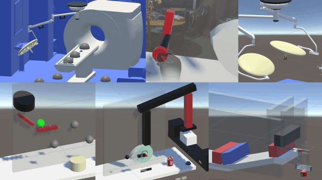
1.1 Exploration
To demonstrate XR’s capability to achieve the above intended outcomes, a hospital light assembly was created that provides a representative example of an articulated engineering system. It allows users to directly interact with the spotlight by moving it around using the handle and observe the resulting motion of the full linked assembly, as shown below.
By grabbing and repositioning the spotlight, users can explore:
- reachable workspace
- kinematic behaviour of the linkage
- and practical implications of articulation at full scale
There are two modes: Fully kinematic motion or Link-by-link articulation.
The interactions can be enhanced by simple additional functionalities. For instance, one can provide stakeholders with a function to modify link lengths (See video below) and let them examine modified assemblies and products without iterative review loops.
1.2 Creation
Another capability could be to create assemblies in situ by intuitively putting together various components using simple, natural interactions. The assembly sequence does not have to be pre-defined, hence giving the user freedom to assemble as they see fit. Instead of only moving the end assembly, users can manipulate individual links, subject to their underlying kinematic constraints. This enables a more design-active form of review, where teams are not only discussing how a mechanism behaves but also exploring how changes to the assembly influence that behaviour.
Conventional CAD provides various tools to create assemblies. With XR providing ways of interacting with a CAD twin at real scale. It could provide a more intuitive, natural way to create assemblies. Fusion 360 provides a toolbox to create joints in assembly, and they classify joints as shown in Table 1:
Table 1: Fusion 360 Joint types and proposed corresponding XR user interface
| Fusion Joint Type | Function | Natural procedure to enable Function | Corresponding XR Interaction |
| Rigid | No motion allowed | Attach the component to the base or another rigid member by welding or bolting | Insert Pin through component (to be fixed) into Fixed link |
| Revolute | Rotate around the origin | Connect the two parts with a pin through aligned holes so one part can rotate about a fixed axis relative to the other. | Insert Pin through component (to be rotated along the pin axis) into fixed or moving link |
| Slider | Move along a single axis | Insert a linear guide between two componentsso it can only translate along one direction. | Insert flat guide (Box collider) through component (to be moved along axis) into fixed link. |
| Cylindrical | Rotate around and move along a single axis | Pass a round rod or shaft through a cylindrical hole or sleeve so it can both slide and rotate about the same axis. | Insert shaft (capsule collider) through component (to be rotated) into fixed link |
| Pin-slot | Rotate around one axis and move along a different axis | Create a slot and place a pin inside itso the pin is guided by the slot while the connected part also pivots or reorients during motion. | Insert flat guide (Box collider) through component 1 (to be moved along axis) and Pin through component 2 (to be rotated along the pin axis) into Fixed link |
| Planar | Move along two axes and rotate around a single axis | Combination of a linear guide to allow linear motion and a pin to rotate around the axis – Constituting a planar motion | Insert Pin (Capsule collider) through component (to be fixed) into Fixed link |
| Ball | Rotate around all 3 axes with no translation | Connect the parts using a ball-and-socket style interface so one component can freely tilt and rotate in all directions while remaining centered at one point. | Insert Sphere through component (to be fixed) into Fixed link |
Programmatically, these joints may be implemented using:
- A collider to give an indication (raise a flag) of whether the pin or a guide has entered the component
- Adding a grab-free transformer/rotational transformer to constrain motions along either or a combination of 3 translations (x, y, z) and 3 rotations (Rx, Ry, Rz).
1.3 Why this matters in design review
The kind of interactions proposed in this module could be particularly useful in stakeholder settings because it could support more grounded discussions and support earlier and more transparent evaluation of:
- workspace coverage
- motion feasibility
- stakeholder co-creation
- mechanism ideation
- real-time design discussion
2. XR-based Physics Informed Systems
This module addresses another important aspect of engineering review: the need to communicate and test the impact of external stimuli on the systems.
In many organisations, the actual working of products is often communicated through screenshots, slide decks, or high-fidelity simulations that require extra time for preparation and thus delay important design decisions.
This module investigates how XR can begin to move beyond that mode of communication by allowing users to observe the influence of external physics-informed stimuli, for example, the impact of payloads, fluids, weights, etc., on the existing system or its role in defining the working of systems.
It thus contains two demos, showing the possibilities of XR-based physics informed systems:
2.1 Impact-driven Systems Design
The first demo presents design tasks in which geometry must be created or arranged in response to external stimuli. That is, the user can observe the impact of the external stimuli on their system and make changes to meet the goal.
These tasks are not intended as abstract demonstrations, but as simplified representations of a real engineering challenge: how to shape or position geometry around motion, interaction, and system behaviour rather than around form alone.
Falling Spheres
In Falling Spheres, users arrange cubes so as to create a maze such that the falling spheres make contact with all targets as they move through the maze.
This captures a familiar design problem in engineering: how to position geometry so that it interacts appropriately with moving bodies under constrained conditions.
From a workflow perspective, it reflects the kinds of reasoning involved in:
- fixture design
- guidance systems
- passive interaction design
- spatial arrangement under dynamic conditions
It highlights how XR can support rapid experimentation with placement, contact, and behavioural outcomes in a more embodied and intuitive way than static screen-based workflows.
Cam Design
In Cam Design, users create a cam profile so that a ram cyclically impacts moving target boxes, mimicking a stamping or packaging process. The user can adjust the shape of the cam and the speed of the cam.
This turns a typically abstract mechanism design task into a directly interactive one, allowing users to shape the geometry to achieve the desired motion behaviour of the follower under the influence of gravity while respecting the shape of cam.
2.2 Behaviour-driven Systems Design
Behaviour-driven systems refer to the design of a system based on a fundamental behaviour/phenomenon generated by the external stimuli that is common throughout the system. For instance, in pneumatic circuits, fluid (external stimuli) moves (as per physics) and pushes the pistons (behaviour), and our task is to design them so they perform the function.
For demonstration, a set of pneumatic circuit components was created that are based on fundamental behaviours and thus provide common functionality throughout, allowing users to explore:
- circuit layout
- component relationships
- actuation logic
- and the broader integration of motion and control
2.3 Why this matters
Both of the above system design methods are relevant to engineering design because many mechanical products are not about geometry in isolation. They are about generating geometry that satisfies physics-driven behaviours.
By making this process interactive, this module explores how XR might help engineers and stakeholders reason more effectively. It supports a more connected design process in which the operation of the products can be discussed alongside external stimuli, rather than as disconnected engineering tasks.
For stakeholder-facing design work, this is particularly useful because it creates a path toward reviewing not just what a system is, but how it functions.
Conclusion
In current industrial practice, there is often a disconnect between what stakeholders want to discuss, what designers can communicate quickly, and what engineers can feasibly modify during a review. XR-based tools create the opportunity to narrow that gap. It can complement existing design pipelines by supporting the stages where teams need to:
- explore alternatives quickly
- evaluate ideas spatially
- communicate motion and function more effectively
- and make design changes before committing to more formal downstream implementation
In this sense, XR-based Mechanisms and Physics-driven systems discussed in this blog can help. It sits between:
- CAD and stakeholder discussion,
- prototype and design change,
- and concept, intent, and engineering implementation.
In our upcoming paper at DESIGN 2026, we will present findings from an industry-led case study on using these tools, demonstrating how XR workflows can support more interactive, stakeholder-driven design processes. The work contributes to a broader research agenda at the DMF Lab: understanding how immersive and interactive technologies can be used for engineering design